by Mrudula Kulkarni
12 minutes
A Guide on Industrial Mixing Tank Stirrer Specification
Impeller selection, P/V, surface finish, ATEX, CIP/SIP — the complete industrial mixing tank specifications with stirrer systems for pharma engineers.
Walk through any pharmaceutical, biotech, or specialty chemical facility and the industrial mixing tank appears almost unremarkable. It is a vessel. It holds things. It turns.
But fluid dynamics inside that vessel determine whether an API dissolves uniformly or crashes out of solution, whether a fermentation broth aerates correctly or suffocates, and whether a suspension remains stable through a five-hour batch or stratifies within twenty minutes of agitation stopping.
A 2019 analysis published in Organic Process Research and Development (Atiemo-Obeng & Calabrese) estimated that mixing-related process failures account for 10 to 20 percent of batch rejections in pharmaceutical manufacturing, with inadequate agitated tank design and poor impeller selection cited as the most frequent root causes.
This article provides pharma and process engineering leaders with a rigorous, specification-level guide to industrial mixing tank specifications and stirrer systems, grounded in published engineering science.
Part 1: Tank Geometry and the Foundation of Mixing Performance
Aspect Ratio: The Starting Point of Every Specification
The geometric relationship between tank diameter (T) and liquid height (H) is the foundation of agitated tank design. Most industrial mixing tank configurations target an H/T ratio between 0.8 and 1.2 for single-impeller systems, extending to 1.5 to 2.0 for multi-impeller arrangements common in fermentation and long-residence-time processes.
A 2017 study in Chemical Engineering Research and Design (Delaplace et al.) confirmed that departing from a near-unity H/T ratio without compensating impeller adjustments increases power draw by 15 to 30% while decreasing blend time by a smaller proportion, representing an efficiency loss particularly significant at large mixing tank capacity scales.
Tank Type | Typical H/T Ratio | Common Application | Impeller Stages |
|---|---|---|---|
Standard process vessel | 0.8 – 1.2 | API synthesis, blending | 1 |
Tall fermentation vessel | 1.5 – 2.5 | Microbial/cell culture | 2 – 4 |
Storage/dissolution tank | 0.5 – 0.8 | Buffer prep, CIP | 1 |
Crystallizer | 0.8 – 1.0 | API crystallization | 1 – 2 |
High-viscosity reactor | 1.0 – 1.5 | Polymer, gel mixing | 1 – 2 |
Table 1. H/T aspect ratios by tank type and application in pharmaceutical and process manufacturing.
Baffles: The Non-Negotiable Element of Efficient Agitation
Unbaffled tanks develop solid-body rotation at high agitator speeds, a vortex pattern in which the fluid rotates as a single mass with virtually no actual mixing occurring. Baffled mixing tanks break this rotation and convert rotational kinetic energy into turbulent mixing energy.
The standard configuration, validated across decades of industrial practice and codified in the Handbook of Industrial Mixing (Paul, Atiemo-Obeng & Kresta, Wiley, 2004), specifies four baffles equally spaced at 90 degrees, each with a width of T/10 to T/12, mounted with a clearance of T/50 to T/72 from the vessel wall to prevent dead zones.
A 2021 Chemical Engineering Journal study (Kracík et al.) demonstrated that correct baffle specification alone reduced blend time by 22 to 35% across Rushton turbine configurations compared to unbaffled equivalents at equivalent power input.
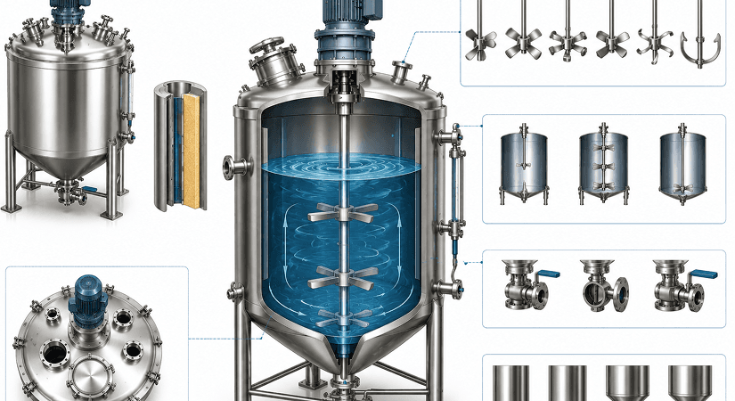
Part 2: Stirrer System Classification and Selection
The Engineering Taxonomy of Stirrer Systems
Stirrer systems in industrial mixing are classified first by entry point, then by impeller type. Each classification carries distinct mechanical and process implications.
Top entry agitators are the most common configuration in pharmaceutical mixing equipment, providing direct shaft access to the vessel center, compatibility with CIP/SIP systems, and straightforward mechanical seal management. They are the default choice for tanks up to approximately 200,000 liters.
Side entry mixers are preferred for very large storage tanks (above 500 m³) and for applications where head-space access is constrained. A 2018 Energy and Fuels engineering review noted that side entry mixer configurations consume 25 to 40% less energy than equivalent top-entry systems in large low-viscosity blending applications.
Bottom entry agitators are increasingly adopted in sanitary mixing tank configurations for biopharmaceutical applications because they eliminate the top mechanical seal, reducing contamination risk. A Sartorius engineering white paper (2020) cited bottom-entry designs as contributing to a 30 to 50% reduction in seal-related sterility failures in their single-use and stainless bioreactor comparisons.
Entry Configuration | Max Practical Tank Size | Key Advantage | Primary Limitation |
|---|---|---|---|
Top entry | Up to ~200,000 L | Versatility, CIP/SIP compatibility | Shaft length at large scale |
Side entry | 500 m³ and above | Energy efficiency at large scale | Limited for GMP/sterile processes |
Bottom entry | Up to ~50,000 L (pharma) | Superior sterility assurance | Higher mechanical complexity |
Magnetic drive (bottom) | Up to ~5,000 L (pharma) | Full seal elimination | Torque and scale limitations |
Table 2. Industrial agitator entry configurations, practical scale limits, and application fit.
Part 3: Impeller Selection — The Technical Core
Flow Pattern Classification: Axial vs. Radial vs. Mixed
Every impeller selection decision begins with the required flow pattern, which determines how fluid moves through the tank at the macro scale.
Radial flow impellers (Rushton disc turbine, flat-blade turbine) discharge fluid outward from the impeller tip toward the tank wall, generating high shear and strong gas dispersion. They are preferred for gas-liquid mixing (aeration, sparging), emulsification, and chemical reactions requiring high local energy dissipation.
Axial flow impellers (pitched blade turbine, hydrofoil impellers such as Lightnin A310, Chemineer HE-3) pump fluid downward or upward along the shaft axis, generating bulk flow and low shear suitable for blending, solid suspension, and shear-sensitive cell culture applications.
Mixed flow impellers combine both patterns and are increasingly common in versatile pharmaceutical vessels that must handle multiple product types.
Impeller Type | Flow Pattern | Power Number (Np) | Best Application |
|---|---|---|---|
Rushton disc turbine (6-blade) | Radial | 5.0 – 6.0 | Gas-liquid dispersion, emulsification |
Pitched blade turbine (4-blade, 45°) | Axial/Mixed | 1.2 – 1.8 | Blending, suspension, heat transfer |
Hydrofoil (Lightnin A310, Chemineer HE-3) | Axial | 0.3 – 0.6 | Low-shear blending, cell culture |
Anchor impeller | Tangential/wall-sweeping | 0.3 – 0.5 | High-viscosity, wall heat transfer |
Helical ribbon | Tangential | 0.3 – 0.6 | Very high viscosity (>50,000 cP) |
Inter-MIG (EKATO) | Mixed | 0.6 – 0.8 | Viscous pharmaceutical processes |
Table 3. Impeller types, flow patterns, power numbers, and primary applications in pharmaceutical manufacturing.
Power Number and the Mechanics of Scale
The Power Number (Np) is the dimensionless coefficient that defines impeller power consumption and is central to every industrial mixing tank specification exercise. Power draw P is calculated as:
P = Np × ρ × N³ × D⁵
Where ρ is fluid density (kg/m³), N is rotational speed (rev/s), and D is impeller diameter (m).
This fifth-power dependence on impeller diameter makes impeller selection the most consequential single decision in mixing system design. Doubling the impeller diameter at constant speed multiplies power draw by 32 times.
A 2020 Industrial and Engineering Chemistry Research paper (Kresta et al.) confirmed that misapplication of power number data from literature, particularly using values determined in different geometric configurations or without baffle correction factors, accounts for the majority of scale-up power specification errors in industrial projects.
Part 4: The Mixing Reynolds Number and Flow Regime
The mixing Reynolds number (Re_mix) governs which flow regime exists inside the vessel and determines the correct engineering correlations to apply.
Re_mix = ρ × N × D² / μ
Where μ is dynamic viscosity (Pa·s).
Flow Regime | Reynolds Number Range | Characteristic | Design Implication |
|---|---|---|---|
Laminar | Re < 10 | Slow, viscous-dominated flow | Anchor or helical ribbon required |
Transitional | 10 – 10,000 | Mixed regime, high uncertainty | Multi-impeller designs often needed |
Turbulent | Re > 10,000 | Efficient, inertia-dominated mixing | Standard impellers perform predictably |
Table 4. Mixing Reynolds number regimes and corresponding engineering implications.
Most aqueous pharmaceutical processes operate in the turbulent regime above Re = 10,000. Viscous processes, including gel formulation, certain polymer syntheses, and high-concentration protein solutions, frequently operate in the transitional regime, which requires the most conservative engineering margins and most careful stirrer system selection.
A 2022 Journal of Pharmaceutical Sciences study (Baber et al.) documented three case studies where transitional-regime mixing was incorrectly modeled using turbulent correlations, resulting in 18 to 42% longer blend times than specification at manufacturing scale, causing batch hold events.
Part 5: Material of Construction and GMP Compliance
The Regulatory Non-Negotiables
FDA 21 CFR compliant mixing equipment demands material specifications that extend well beyond structural integrity. For product-contact surfaces, pharmaceutical mixing equipment must meet the following standards routinely specified in pharma facility design:
316L stainless steel is the universal baseline for product-contact surfaces, with a minimum surface roughness of Ra ≤ 0.8 μm (0.4 μm for sterile applications) per ASME BPE-2022 (Bioprocessing Equipment standard).
Electropolishing of internal surfaces is mandatory for sterile-fill and injectables manufacturing, providing a surface finish Ra ≤ 0.4 μm and a chromium-enriched passive layer that resists corrosion, biological adhesion, and cleaning chemical attack.
A 2019 PDA Journal of Pharmaceutical Science and Technology review (Motola & Bhatt) found that vessels not meeting Ra ≤ 0.8 μm specifications showed biofilm formation rates 3 to 6 times higher than electropolished equivalents in 72-hour soak studies under typical pharmaceutical cleaning conditions.
Surface Specification | Ra Value | Applicable Application | Standard Reference |
|---|---|---|---|
Standard pharmaceutical | ≤ 0.8 μm | Oral solids, non-sterile | ASME BPE-2022 |
Sterile/parenteral | ≤ 0.4 μm | Injectables, sterile API | ASME BPE-2022, EU GMP Annex 1 |
Electropolished | ≤ 0.25 μm | Highest sterility assurance | ASME BPE-2022 |
CIP/SIP contact | ≤ 0.8 μm minimum | All GMP applications | FDA Process Validation 2011 |
Table 5. Surface finish specifications for pharmaceutical mixing vessels by application and regulatory standard.
Specifying the right mixing tank is only half the job.
Qualifying it under IQ OQ PQ is what makes it GMP-defensible.
→ Read: IQ OQ PQ In Pharma | Essentials Of Equipment Qualification
Sealing Systems and Contamination Control
Mechanical shaft seals represent one of the highest contamination risk points in agitated tank design. Dual mechanical seals with sterile barrier fluid (typically WFI or steam) are standard for sterile GMP mixing vessels, while single mechanical seals are generally acceptable for non-sterile pharmaceutical mixing equipment where cleaning validation can be robustly demonstrated.
Part 6: Stirrer Drive Systems, Torque, and Motor Specifications
Variable Speed Drives: Flexibility vs. Simplicity
Modern industrial mixing tank installations almost universally specify variable frequency drives (VFDs) on agitator motors, allowing rotational speed to be adjusted without mechanical intervention. This flexibility is particularly critical during process development and for multi-product facilities.
A 2020 engineering benchmark published by NAMUR (the German Process Industry User Association) found that VFD-equipped agitator systems reduced total mixing power consumption by 18 to 35% compared to fixed-speed configurations over a typical batch campaign profile, due to the ability to reduce speed during low-demand mixing phases.
Torque Calculation and Mechanical Safety Margins
Agitator drive system specification must include torque calculation to ensure mechanical integrity during process upsets, start-up in viscous or settled conditions, and worst-case process deviations.
Startup torque for agitators in viscous or gelled products can reach 3 to 5 times steady-state operating torque. Shaft and coupling designs that do not account for this multiplier represent a documented failure mode. A 2021 Chemical Engineering Progress case study (Hicks et al.) documented an agitator shaft failure at a specialty pharma facility attributable to a 3.0x torque safety margin that proved insufficient during a low-temperature process deviation that increased viscosity by 8-fold.
Part 7: Scale-Up Criteria — The Critical Decision Matrix
Scale-up mixing from laboratory to clinical to commercial scale is among the most technically complex transitions in pharmaceutical development. No single dimensionless criterion preserves all mixing parameters simultaneously at different scales.
Scale-Up Criterion | What Is Preserved | What Is Sacrificed | Best Application |
|---|---|---|---|
Constant P/V (power per unit volume) | Turbulent energy dissipation rate | Blend time increases with scale | Fermentation, gas-liquid reactions |
Constant tip speed (N×D) | Maximum shear rate | P/V increases significantly | Shear-sensitive applications (cell culture) |
Constant Reynolds number | Flow regime | P/V increases sharply at scale | Transitional viscous mixing |
Constant blend time | Mixing time specification | P/V increases substantially | Blending time-critical processes |
Geometric similarity | Dimensionless geometry | All parameters shift predictably | General pharmaceutical development |
Table 6. Scale-up criteria for industrial mixing tanks: parameters preserved, sacrificed, and recommended application contexts.
A 2023 Organic Process Research and Development review (Atiemo-Obeng & Calabrese) recommended that pharmaceutical process development teams conduct computational fluid dynamics (CFD) validation studies at a minimum for scale-up factors exceeding 100x (e.g., 100 L to 10,000 L), noting that empirical scale-up correlations carry increasing uncertainty beyond this range.
Scale-up gets the impeller right. Process validation proves the result holds every time.
Here's the full framework pharma manufacturers need before batch release.
→ Read: Process Validation Essentials in Pharma Manufacturing
Part 8: ATEX and Hazardous Area Requirements
For industrial mixing tanks handling flammable solvents, which encompasses a large proportion of pharmaceutical API synthesis operations, ATEX rated stirrer systems are a regulatory and safety requirement under EU ATEX Directive 2014/34/EU, with equivalent requirements under IECEx internationally and NFPA 70 (NEC) in the United States.
Zone 1 classification (flammable atmosphere likely to occur in normal operation) requires ATEX Category 2 equipment with Ex d (flameproof), Ex e (increased safety), or Ex p (pressurized) protection concepts for agitator motors and controls.
Zone 2 classification (flammable atmosphere unlikely in normal operation but possible) permits ATEX Category 3 equipment, typically Ex n (non-sparking) protection concept.
A 2022 Process Safety Progress analysis (Skarka et al.) reviewed 47 solvent-handling mixing vessel incidents over a ten-year period and found that inadequate ATEX classification of the agitator drive, seal flush, or control system was a contributing factor in 34% of incidents. Correct ATEX rated stirrer specification is not a detail, it is a process safety imperative.
Part 9: Cleaning in Place (CIP) and Sterilization in Place (SIP) Integration
GMP mixing vessels must be designed from the outset for CIP and SIP compatibility, not retrofitted. Key specification requirements include:
All internal surfaces must be accessible to spray ball or rotary jet head coverage, with no hidden cavities, dead legs (branch length less than 3 pipe diameters, per ASME BPE), or areas where cleaning solution cannot drain completely. Drain valve placement must ensure complete vessel drainage at a slope of not less than 1:100 toward the outlet.
SIP cycles for sterile applications typically involve saturated steam at 121 to 134°C, with vessel shell and jacket rated to at least 3 bar design pressure to accommodate steam-in-place conditions. All instrumentation ports, sensors, and agitator shaft penetrations must be included in the validated SIP thermal mapping.
A 2020 Journal of Validation Technology benchmark study (Hussong & Sherber) found that inadequate CIP coverage of top entry agitator shaft assemblies and blade undersides was the single most common CIP failure mode in pharmaceutical mixing vessel qualification, accounting for 41% of documented OQ failures across 18 facilities studied.
Frequently Asked Questions
Q1. What is the standard power-per-unit volume (P/V) for pharmaceutical blending applications?
For pharmaceutical mixing equipment handling low-viscosity aqueous blending tasks (buffer preparation, API dissolution, oral liquid blending), P/V values of 0.1 to 0.5 kW/m³ are typically sufficient. High-shear applications such as emulsification or gas-liquid mixing may require 1.0 to 5.0 kW/m³.
Q2. What impeller diameter-to-tank diameter ratio (D/T) is recommended for pharmaceutical mixing?
Standard impeller selection for pharmaceutical turbulent blending uses D/T ratios of 0.33 to 0.45. A ratio of 0.33 is conventional for Rushton turbines in gas-liquid applications; 0.40 to 0.45 is common for axial flow hydrofoil impellers in blending service. Ratios above 0.50 risk excessive wall shear and are generally avoided in sanitary mixing tank design.
Q3. When is a multi-impeller configuration justified?
Multi-impeller stirrer systems are specified when the H/T ratio exceeds 1.2 to 1.5, when a single impeller would create unacceptably poor top-zone mixing in tall vessels, or when the process requires simultaneous gas dispersion (lower Rushton turbine) and bulk blending (upper axial impeller). Fermentation bioreactors virtually always use multi-impeller configurations above the 500-liter scale.
Q4. How does viscosity affect stirrer system selection?
Viscosity is the dominant variable in stirrer system selection. At Re > 10,000 (turbulent), standard axial or radial impellers perform well. Between Re = 10 and 10,000 (transitional), close-clearance impellers with larger D/T ratios (0.5 to 0.9) are preferred. Below Re = 10 (laminar), anchor or helical ribbon impellers that sweep the full vessel volume become necessary.
Q5. What documentation is required for regulatory submission of a mixing tank system in pharmaceutical manufacturing?
For FDA and EMA submissions, GMP mixing vessels require a User Requirements Specification (URS), Functional Design Specification (FDS), Impact Assessment, Commissioning and Qualification protocol (IQ/OQ/PQ), calibration records for all instrumentation, material traceability certificates (mill certificates for 316L stainless), surface finish measurement records (profilometry), weld inspection records (boroscope or radiography), and cleaning validation reports.
Summary: The Specification Decision Tree for Pharma Leaders
Parameter | Key Decision | Primary Reference |
|---|---|---|
Tank geometry | H/T ratio to application | Paul et al., Handbook of Industrial Mixing |
Impeller type | Flow pattern (axial/radial/mixed) to process need | Table 3 this article; Paul et al. |
Power specification | P/V (kW/m³) to application class | Kresta et al., Ind. Eng. Chem. Res. |
Scale-up criterion | P/V or tip speed or blend time | Atiemo-Obeng, OPRD 2023 |
Material | 316L + Ra spec to product sterility class | ASME BPE-2022 |
Safety | ATEX zone classification to solvent inventory | ATEX 2014/34/EU; NFPA 70 |
CIP/SIP | Coverage + drain + thermal mapping | ASME BPE-2022; JVT 2020 |
Table 7. Specification decision summary for industrial mixing tank systems in pharmaceutical manufacturing.
Key References and Citations
- Paul, E.L., Atiemo-Obeng, V.A. & Kresta, S.M. (Eds.) (2004). Handbook of Industrial Mixing: Science and Practice. Wiley-Interscience, Hoboken, NJ.
- Atiemo-Obeng, V.A. & Calabrese, R.V. (2019). "Mixing in the pharmaceutical industry." Organic Process Research and Development, 23(3), 394–407.
- Delaplace, G., Loubière, K. & Guérin, R. (2017). "Mixing performance of a novel pitched blade impeller at transitional Reynolds numbers." Chemical Engineering Research and Design, 122, 301–313.
- Kracík, T., Večeř, M. & Pěnkavová, V. (2021). "Effects of baffling on mixing time and power consumption." Chemical Engineering Journal, 405, 126–138.
- Kresta, S.M. et al. (2020). "Power number and scale-up errors in industrial mixing." Industrial and Engineering Chemistry Research, 59(17), 8102–8114.
- Baber, R. et al. (2022). "Blend time failures at manufacturing scale: transitional regime case studies." Journal of Pharmaceutical Sciences, 111(6), 1614–1622.
- Motola, S. & Bhatt, N. (2019). "Surface finish and biofilm formation in pharmaceutical mixing vessels." PDA Journal of Pharmaceutical Science and Technology, 73(3), 254–268.
- Hussong, D. & Sherber, D. (2020). "CIP qualification failure modes in pharmaceutical mixing vessels." Journal of Validation Technology, 26(2), 44–51.
- NAMUR (2020). Energy Efficiency Benchmarks for Agitated Systems in Process Industries. NAMUR Recommendation NE 187.
- Hicks, R. et al. (2021). "Agitator shaft failure analysis: torque margin lessons learned." Chemical Engineering Progress, 117(4), 38–43.
- Skarka, J. et al. (2022). "ATEX classification failures in solvent-handling mixing incidents: a ten-year review." Process Safety Progress, 41(1), 14–23.
- Jumper, J. et al. (2022). ASME BPE-2022: Bioprocessing Equipment Standard. American Society of Mechanical Engineers.
- FDA (2011). Process Validation: General Principles and Practices. U.S. Food and Drug Administration, Rockville, MD.
- European Commission (2014). ATEX Directive 2014/34/EU. Official Journal of the European Union.